1 Axes Controller Board - Introduction -
Standard 3D printers rely on simple Cartesian kinematics and open-loop stepper motors. However, upgrading to a 5-axis non-planar printing system introduces heavy custom mechanisms, significant rotational inertia, and the need for absolute spatial accuracy. To overcome this need, the Axes Controller Board (ACB) borns. The architectural philosophy behind the ACB is straightforward: strict computational decoupling. The Raspberry Pi 5 acts as the brain, performing the heavy mathematics for S-profile interpolation, path planning, GCode parsing. Meanwhile, the ACB acts as the working force, executing the motor commands in hard real-time and reacting to sensor feedback within fractions of a millisecond. Computational decoupling is applied on the microcontroller as well: the CPU is utilized only for control computations, while data acquisition is devoted to DMA or Timers.
2 Hardware Design
The PCB was designed to be highly integrated, eliminating messy wiring. Instead of connecting the Raspberry Pi via standard USB cables, the Pi mounts directly onto the ACB as a daughterboard and the stepper motors’ drivers as well.
The main power comes from a 400W AC to 12V DC power supply unit, that results to be the only cable to plug to the AC.
2.1 Power Supply Stage
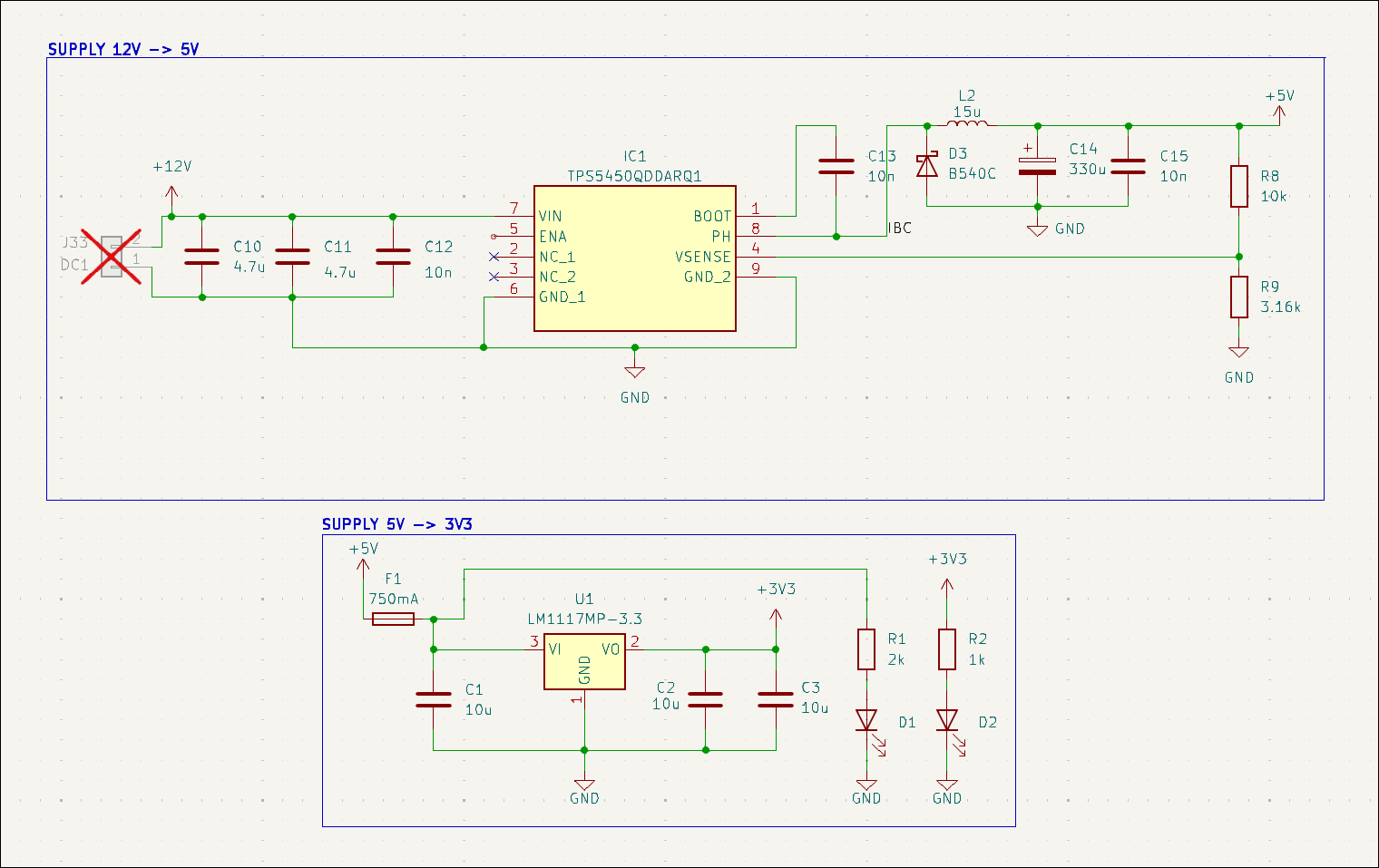
In order to deliver power and eliminate ground loops, a custom onboard DC-DC buck converter steps down the main power supply and feeds clean 5V and 3.3V power to Raspberry Pi directly through its GPIO headers and the STM32H7 microcontroller respectively.
For this case, TPS5450-Q1 from Texas’ Instruments is used. This IC features up to 36V DC input and, most important, up to 5A as output current at 5V. This is a fundamental characteristic because of the high sensitivity of the Raspberry’s GPIO supply. Indeed, 5.1V is required in order to be robust over voltage drops, for example during compilations or heavy computations periods. Then, a 5V to 3.3V LDO is used in order to step down the main DCDC supply to a stable and reliable 3.3V for the microcontroller and sensors.
2.1.1 Power Consumption and Thermal Considerations
The Raspberry Pi 5 under heavy multi-core load can experience current spikes up to 3.0A at 5V (\(\approx 15\)W). The TPS5450-Q1 ensures a maximum continuous output of 5A (25W), providing a robust 40% safety margin. This headroom is critical to prevent voltage drops that would otherwise trigger the Pi’s under-voltage mechanism or cause unexpected CPU reboots.
On the 3.3V logic side, the STM32H7 running at its peak frequency of 550 MHz, combined with the SPI rotary encoders and linear sensors supply, draws an estimated maximum continuous current of 300–400 mA. Because this stage is powered via a linear LDO regulator fed by the 5V rail, the IC must physically dissipate the voltage drop as heat. The theoretical maximum power dissipation \(P_{diss}\) is calculated as:
\[P_{diss} = (V_{in} - V_{out}) \times I_{load} = (5.0\text{V} - 3.3\text{V}) \times 0.4\text{A} \approx 0.68\text{W}\] While 0.68 W is a manageable thermal load for a modern SMD package, it requires careful thermal routing. To handle both the DC-DC switching losses and the LDO linear dissipation without relying on external heatsinks, the ACB’s 4-layer PCB architecture leverages its solid internal GND layers. Various thermal vias connect the ICs’ exposed pads directly to these copper planes, effectively turning the entire board into a massive thermal relief.
The schematic is configured as shown in Figure 1.
2.2 Motor Drivers
For the actuators, the stepper motor drivers are soldered directly on the board, keeping the high-current switching traces as short as possible to drive the Moons’ C17HD4010201N stepper motors efficiently. The selected drivers are the consolidated TMC2209.
Stepper motors are used solely on positioning axes, such as Z, Pitch (A) and Yaw (C), where Pitch and Yaw are the actuated rotations of the printing plate as the 2 additional rotation axes.
For the X and Y axes, which are the movement axes dedicated to the actual printing evolution, DC brushed motors are mounted: they allow a more precise and industrial-grade control, by sacrificing noise due to the gear box stage. DC motors are driven by double-H-bridge drivers configured as IBT-4.
2.3 Encoders
On the sensor side, the board interfaces with two distinct feedback systems to close the control loops. The RLS linear magnetic encoders (RLC2IC) output standard A/B quadrature signals, which are wired directly to the UA667 driver, which outputs a differential signal to the STM32’s hardware encoder timers (TIM2 and TIM5), allowing the hardware to track absolute position with zero CPU overhead. Meanwhile, the AS5048A rotary encoders are read by leveraging DMA along SPI communication. Due to DC motors and long cables, it was not possible to implement a daisy-chain architecture between rotary encoders. Each AS5048a communicates on its dedicated SPI interface.
2.3.1 Signal Integrity and Noise Immunity
Routing high-speed SPI signals across a 3D printer frame poses significant Electromagnetic Interference (EMI) challenges, particularly because the sensor cables run parallel to the unshielded power wires of both stepper motors and DC actuators. SPI is a single-ended protocol, making it naturally susceptible to capacitive coupling and crosstalk.
To mitigate these issues and preserve signal integrity over cable lengths up to 50cm, source termination resistors (33 \(\Omega\)) are placed in series on the SCK, MOSI, and CS lines directly at the microcontroller outputs. These resistors act as impedance matching elements, dampening high-frequency harmonics and limiting the slew rate. This prevents signal reflections (ringing) that could cause false clock edges and data corruption. Coupled with the lowered baud rate on longer branches (e.g., 500kbps), this termination strategy ensures reliable data transmission in a harsh electromechanical environment.
2.3.2 Technical Constraints and Specifications
To guarantee the reliability of the control loops, the mechanical and electrical integration must strictly adhere to the operating limits of both sensor families.
The AS5048A rotary encoders require a clean 3.3V power supply and communicate via a high-speed SPI bus, outputting a 14-bit absolute angular position. This provides a native resolution of \(0.0219^\circ\) per step (16384 steps per revolution). The 16-bit SPI payload embeds not only the data but also parity and hardware error flags. Mechanically, the Hall-effect sensor demands strict diametrical alignment with its magnet. The air gap between the IC package and the magnet surface is a critical parameter: it must be maintained strictly between 0.5mm and 2.0mm. An air gap narrower than 0.5mm physically saturates the sensor (triggering a Magnetic Field High, or MIGH, hardware error), whereas an excessive distance leads to signal loss (Magnetic Field Low, MGL error), instantly invalidating the velocity feedback to the PID.
Conversely, the RLS RLC2IC linear encoders are fed by the 5V rail and rely on a purely hardware-driven interface, outputting standard A/B quadrature digital signals. These signals provide an exceptional linear resolution of 5\(\mu\)m. However, this extreme sensitivity introduces severe mechanical installation constraints. The sensor readhead must move over the magnetic scale with a nominal ride height (air gap) typically restricted to a fraction of a millimeter (around 0.1mm to 0.4mm) and tightly controlled pitch, roll, and yaw tolerances. Any mechanical deflection along the axes that alters this microscopic gap can cause quadrature pulse loss, which would irreversibly corrupt the absolute positioning tracked by the STM32 hardware timers.
2.4 Microcontroller
The chosen microcontroller is an STM32H723ZGT6, representing the cutting edge of the STM32 products for complex mechatronic applications. It offers:
32-bit Arm Cortex-M7 CPU with native single and double-precision Floating Point Unit (FPU) support;
Maximum core frequency of 550 MHz;
4 DMA controllers and 24 advanced hardware timers;
High-speed communication interfaces (SPI, I2C, USART).
3 PCB Design
Regarding the PCB design, there are no strict dimensional constraints since the board is intended for a large-scale, high-end 3D printer. Nevertheless, the board is designed to be highly compact, easily mountable, and optimized for harsh electromechanical environments.
3.1 Layers Layout
To ensure signal integrity and robust power delivery, the ACB is structured on a 4-layer PCB. The layer stackup is assigned as minimizing ground loop distances, provide passive electromagnetic shielding, and avoid voltage drops on critical supply lines:
Front Layer: Dedicated to component placement and critical high-speed signal routing (e.g., SPI lines). The unused area is flooded with a continuous GND copper pour.
Inner Layer 1: Acts as a dedicated, solid GND plane. This is crucial to provide an uninterrupted, ultra-short return path for high-frequency digital signals, effectively minimizing the loop inductance.
Inner Layer 2: Acts as a split power plane, partially covered by 3.3V and 5V copper zones, as shown in 3.
Back Layer: Used for secondary signal routing and power traces crossing, fully flooded with a GND pour tightly stitched to the other GND layers via arrays of vias.
3.2 Ground Decoupling and Star Topology
A mixed-signal board dealing with heavy inductive loads requires aggressive noise management. The stepper motors and DC actuators draw high, pulsed currents that can cause severe "ground bounce" if their return paths overlap with the sensitive 3.3V logic.
To solve this, the PCB implements a Star Grounding Topology. The high-power ground (PGND), used by the TMC2209 stepper drivers and external IBT-4 connectors, is physically decoupled from the digital ground (SGND) used by the STM32 and the SPI encoders. These two ground planes are routed separately and tie together at exactly one single node: the negative terminal of the main 12V power supply input. This guarantees that the noisy return currents from the motors flow directly back to the power supply without ever crossing or polluting the microcontroller’s zero-volt reference.
3.3 DC-DC Converter Layout Rules
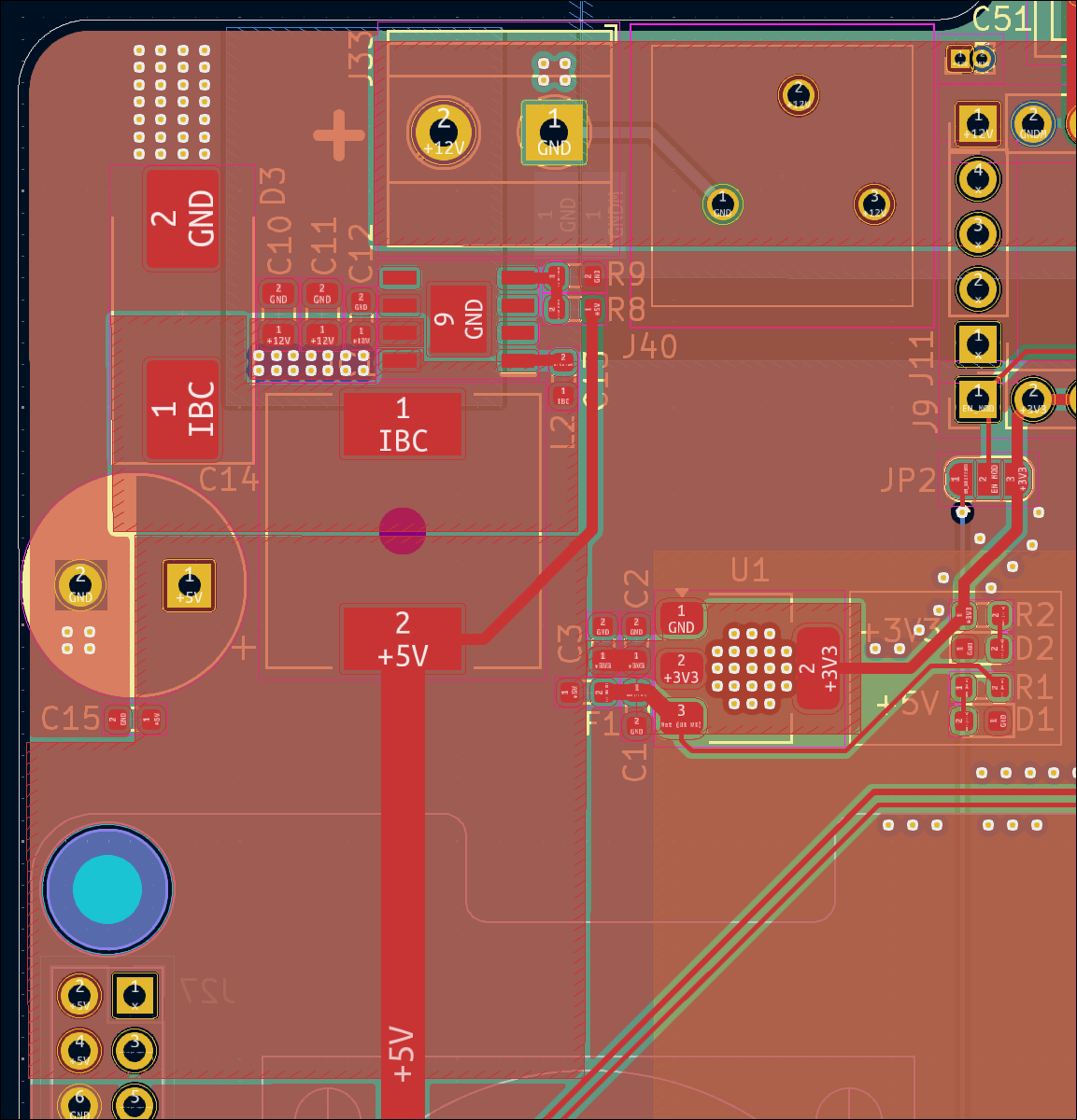
The switching nature of the TPS5450-Q1 buck converter generates aggressive high-frequency voltage and current transients. To prevent supply noise and interferences, layout guidelines are shown in Figure 2:
Minimized High-Frequency Loops: The input decoupling capacitors, the catch diode, and the power inductor are placed as physically close to the IC pins as possible. This minimizes the parasitic inductance of the switching loop, drastically reducing voltage ringing and EMI.
Copper Polygons over Traces: In the power stage, standard thin PCB traces are completely avoided. Instead, wide copper polygons (zones) are used to connect the 12V input, the 5V output, and the switching node.
Thermal Management: Besides increasing the current-carrying capacity for the 5A maximum load, these massive copper polygons act as integrated heatsinks, helping the thermal dissipation away from the IC’s exposed pad and spreading it across the board’s internal layers through thermal vias.
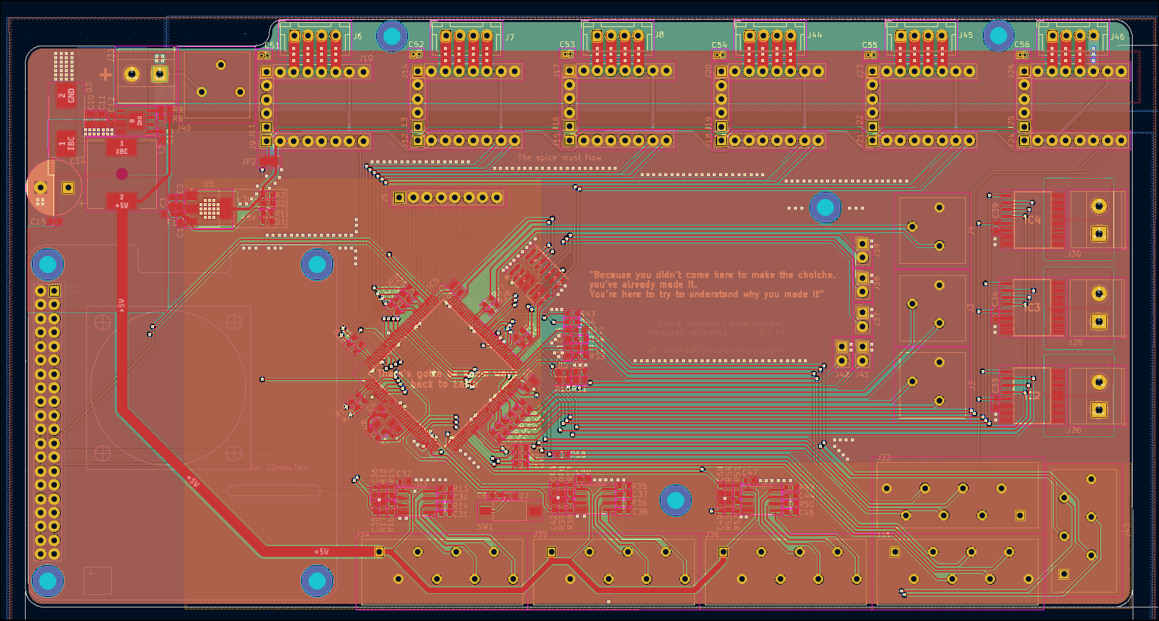
TMC2209 drivers are separated from the 3V3 side. Furthermore, the inner layer with the orange 3V3 zone is shown in order to bring supply to microcontroller and rotary encoders connectors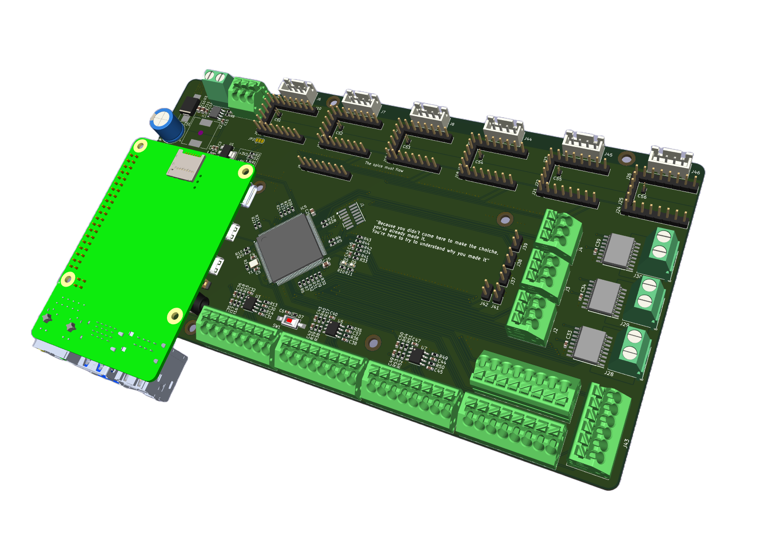
4 Firmware Architecture
The firmware is written entirely in bare-metal C. A Real-Time Operating System was avoided to eliminate the unpredictable overhead and context-switching delays that could affect the strict timing requirements of the control loop and thus to have all the possible control over the workflow. The development environment does not have many requirements: the entire codebase was written in Visual Studio Code and compiled, flashed, and debugged using the OpenOCD tool.
The following structs are implemented:
typedef struct {
    float _kp, _ki, _kd;
    float _setpoint;
    float _integral;
    float _last_error;
    float _output_limit;
    float _output;
    float _last_D;
    float _anti_windup_limit;
} PID;

typedef struct {
    int32_t _raw_value;
    float _converted_value;
    float _velocity;
    float _offset;
    float g_ratio;
    float _last_raw_pos;
    float _last_converted_value;
    float _last_velocity;
    float _acceleration;
    int32_t _turns;
} Encoder;

typedef struct {
    Encoder *_enc_rot;
    Encoder *_enc_lin;
    PID _pid_pos;
    PID _pid_vel;
    float _target_pos;
    float _target_vel; // from feedforward
    float _last_vel;
    float _ka;
    volatile uint32_t *_pwm_register;
} Axis;

typedef struct {
    Encoder *_enc_rot;
    float _target;
    float steps_per_unit;
    float _current_speed_hz;
    float _target_speed;
    float _last_error;
    uint8_t _dir;
    uint8_t _in_position;
} Stepper;
4.1 Decoupling Data Acquisition from Control
In a 10 kHz control loop, the CPU has an absolute maximum window of 100 microseconds to complete all its tasks. Wasting CPU clock cycles waiting for an SPI bus to shift bits serially is unacceptable for this case. Therefore, it is strictly decoupled data acquisition from the actual motor control logic.
The STM32H7 CPU is dedicated 100% to running the PID algorithms and calculating the next motor commands. For the motors, querying the SPI rotary encoders is fully offloaded to the Direct Memory Access (DMA) controller: the CPU triggers a non-blocking read and immediately processes the data only upon the DMA transfer complete interrupt.
4.2 Clock Configuration
To strictly meet the deterministic constraints of the hard real-time motor control, the clock tree was configured to extract maximum performances. The main Phase-Locked Loop (PLL) multiplies the internal oscillator to drive the Cortex-M7 core at its peak 550 MHz.
The peripheral buses (APB1, APB2, APB3, APB4) are divided down to run at 137.5 MHz. However, the STM32H7 architecture automatically doubles the clock frequency for the hardware timers, meaning that all motor control timers (such as TIM1 for the DC motors and TIM4, TIM8, TIM15 for the steppers) operate at a 275 MHz base clock. This extremely high resolution is crucial to calculate dynamic Auto-Reload Register (ARR) values, enabling smooth PWM step generation for the stepper drivers, even at extremely low rotational speeds.
4.3 SPI and DMA
For the data acquisition side, the SPI buses are explicitly mapped and clocked to optimize reliability across different cable lengths:
SPI1 and SPI2 (dedicated to the AS5048A rotary encoders) are fed by a 64MHz peripheral clock. SPI1 operates at a stable 1Mbps (using a 64 prescaler) for the shorter cables, while SPI2 was deliberately slowed down to 500kbps (128 prescaler) to effectively suppress electromagnetic reflections and ringing on the longer 50cm cables reaching the X-axis.
SPI3 acts as the 1 MHz Full-Duplex slave interface to seamlessly exchange target coordinates and telemetries with the Raspberry Pi 5.
SPI4 and SPI5 are devoted to A and C axes and they are configured as SPI2.
By leveraging the built-in DMA controllers, the 550MHz CPU is completely freed from the overhead of polling bits on the SPI buses. Linear encoders are directly interfaced with the hardware Timers, meaning the positional CNT register is always instantly available to be read. As a result, the core focuses exclusively on dealing the float mathematics of the multi-axis PID loops, fully exploiting the native hardware FPU.
4.4 Rotary Encoders Acquisition
AS5048a run via SPI, so the 0x3FFF hexadecimal mask is used to get rid od the two most significant bits of the 16-bit word (Bit 15 for parity, and Bit 14 for hardware errors). This safely isolates the pure 14-bit positional data, yielding an integer between 0 and 16383. The resulting value is explicitly cast to a float and multiplied by the resolution factor (\(360^\circ / 16384\)) to directly convert the raw data into a precise floating-point angle in degrees.
void update_rotary_encoder(Encoder *enc, uint16_t raw_spi, float dt){
  if (raw_spi & 0x4000) {
    return;
  }
  float new_pos = (float)(raw_spi & 0x3FFF) * (360.0f / 16384.0f);
  float diff = new_pos - enc->_last_raw_pos;
  if (diff > 180.0f) {
    diff -= 360.0f;
    enc->_turns--;
  }
  else if (diff < -180.0f) {
    diff += 360.0f;
    enc->_turns++;
  }
  enc->_last_raw_pos = new_pos;
  float total_pos_deg = (enc->_turns * 360.0f) + new_pos;
  enc->_converted_value = (total_pos_deg - enc->_offset)  / enc -> _g_ratio ;
  float instant_vel = diff / dt;
  enc -> _velocity = (enc->_velocity * 0.99f) + (instant_vel * 0.01f);
  enc -> _last_converted_value = enc->_converted_value;
  enc -> _acceleration = enc -> _acceleration * 0.95f + ((enc -> _velocity - enc -> _last_velocity) / dt) * 0.05f;
  enc -> _last_velocity = enc -> _velocity;
}
Regarding the mounting on DC motors, the sensors are mounted directly on the high-speed motor shaft, strictly before the planetary gearbox. The amplified resolution given by the 27:1 and 24:1 mechanical reductions yields an effective linear resolution at the belt of approximately \(0.09~\mu m\). The fast 10kHz inner loop acts as an high-resolution damper, neutralizing micro-vibrations before they propagate through the gearbox, while the slower 1kHz outer loop utilizes the 5\(\mu\)m linear scale strictly as an absolute, backlash-free reference.
The stepper motors control runs at 10kHz as well, thanks to DMA and SPI combination for rotary encoders.
4.4.1 DMA and L1 Cache Management
Relying heavily on DMA inside a high-performance Cortex-M7 core introduces an important hardware challenge: cache coherence. Because the DMA streams the incoming SPI sensor data directly into the RAM, the CPU’s L1 Data Cache remains completely unaware that the underlying memory has changed. If the CPU tries to read the sensor data immediately, it will fetch old values from its fast cache rather than the updated values from RAM.
To solve this, manual cache invalidation commands (SCB_InvalidateDCache_by_Addr) are implemented inside the DMA complete callbacks. This forces the CPU to discard its cached memory and fetch the fresh positional bytes directly from RAM before feeding them to the PID controllers.
Furthermore, the DMA is configured for the full-duplex SPI communication with the Raspberry Pi. Initially, using the DMA in "Circular" mode caused FIFO tearing and checksum failures, because the DMA would begin fetching the next packet while the CPU was still updating the current one. This was fixed by switching the DMA to "Normal" mode and manually re-arming it only inside the completion callback, ensuring the Raspberry Pi always reads perfectly atomic and synchronized data packets.
Moreover, the Cortex-M7 cache operates on 32-byte cache lines. If a DMA buffer shares a cache line with standard CPU variables, performing a manual cache invalidation could accidentally wipe out adjacent data. To prevent this memory corruption, a dedicated, uninitialized memory section is defined in the linker script (STM32H723XG_FLASH.ld) forced to a strict 32-byte alignment:
.dma_buffer (NOLOAD) :
  {
    . = ALIGN(32);
    *(.dma_buffer)
    . = ALIGN(32);
  } >RAM_D1
uint8_t spi3_rx_buf[96] __attribute__((section(".dma_buffer"), aligned(32)));
uint8_t spi3_tx_buf[96] __attribute__((section(".dma_buffer"), aligned(32)));
void HAL_SPI_TxRxCpltCallback(SPI_HandleTypeDef *hspi) {
if (hspi->Instance == SPI3) {
SCB_InvalidateDCache_by_Addr((uint32_t *)spi3_rx_buf, 96);
// Processing
}
}4.5 Motor Control Execution
The heart of the system is a hardware timer (TIM6) interrupt that ticks precisely at 10kHz. Inside this hard real-time routine, two different types of actuators are handled at two different frequencies.
4.5.1 DC Motors
For the brushed DC motors, the control relies on a cascaded PID architecture. The outer position loop operates at 1kHz, reading the absolute position from the high-resolution linear quadrature encoders. This loop computes a corrective velocity to compensate for mechanical backlash and belt stretch, which is then summed with the velocity feedforward target sent directly by the Raspberry Pi. The inner velocity loop executes strictly at 10kHz, computing the dynamic error against the rotary encoders’ readings acquired via the SPI-DMA pipeline. The final output determines the PWM duty cycle sent to the external IBT-4 dual H-bridge drivers. To ensure mathematical stability and prevent integral saturation whenever the motors hit their maximum physical speed or PWM limits, a robust anti-windup algorithm is integrated into both control loops.
4.5.2 Stepper motors
For the stepper motors, the firmware runs a single P loop at 10kHz, computing the positional error dynamically against the rotary encoders’ readings acquired via the SPI interface. The algorithm converts the required speed into a step frequency and adjusts the Auto-Reload Register (ARR) of the hardware timers. It ensures a smooth rotation of the stepper motor without delivering a CPU-driven pulses train.
However, controlling stepper motors in a closed-loop system introduces specific physical challenges that standard P controllers cannot handle alone:
Inertia and Braking: Stepper motors can easily overshoot the target if commanded to a fast stop, causing oscillation. To prevent this, the firmware implements a predictive braking algorithm. It dynamically limits the maximum allowed speed based on the remaining distance, forcing the motor to absorb the kinetic energy and decelerate smoothly before reaching the target.
The spring effect and Holding Torque: When a stepper holds its position, the electrical elasticity of the coils (acting like virtual springs) and the natural noise of the high-resolution encoders can trick the control law into making high-frequency corrections. To ensure absolute stillness, the algorithm implements an hysteresis check. Once the motor is within half a physical step of the target, the active control loop goes to sleep, relying entirely on the motor driver’s natural Holding Torque. The loop only wakes up and applies a correction if an external force physically pushes the axis out of its resting tolerance.
Regarding the Z axis, it is the only open-loop controlled axis. This decision stands on the fact that its blocking reduction introduce a natural stability which reduces the performance gap with the closed-loop control. Moreover, the mechanical mounting of the rotary encoder requires complex design due to motor shaft possibile movements.
4.6 Raspberry Pi SPI Full-Duplex Communication
To ensure the synchronized flow of trajectories, the STM32H7 and the Raspberry Pi 5 communicate via a 1 MHz full-duplex SPI link. Since the Raspberry Pi acts as the SPI Master, data exchange happens simultaneously: while the Pi sends the next trajectory targets (positions and feedforward velocities), the STM32 returns the current telemetries (actual positions, measured velocities, and tracking errors). This procedure loops at 1kHz.
To ensure micrometric precision, the exchanged data structures must be perfectly aligned in memory. Because the Raspberry Pi (Cortex-A76) and the STM32 (Cortex-M7) process memory alignment differently, relying on default compiler behavior results in misaligned bytes across the SPI bus, leading to catastrophic position commands. To solve this, strict memory padding and compiler pragmas (#pragma pack(push, 1)) are implemented. This guarantees that both devices interpret the fixed 96-byte payload identically. Furthermore, the checksum calculation deliberately ignores the padding bytes to prevent undefined memory states from triggering false-positive data corruption errors.
4.7 Checksum Calculation
Given the noisy electromagnetic environment generated by the brushed DC motors and stepper drivers, the SPI communication lines are highly susceptible to electromagnetic interference (EMI). To guarantee data integrity and prevent the actuators from executing corrupted position commands, a lightweight but robust checksum mechanism was implemented.
The firmware uses a Longitudinal Redundancy Check (LRC) based on a sequential XOR operation. The choice of the XOR algorithm is strategic: it requires a single CPU clock cycle per byte on the Cortex-M7 architecture, ensuring that the checksum verification does not add computational overhead.
Before transmission, the STM32 treats the 96-byte packet as a contiguous array of unsigned 8-bit integers. The algorithm loops through the first 69 active bytes, which include the start byte, the sequential message ID, and all the 32-bit floating-point telemetries, computing the cumulative XOR value. The resulting 8-bit checksum is then injected into the check field of the packet. Crucially, the calculation deliberately excludes the trailing 26 bytes of padding. Since these padding bytes contain uninitialized RAM data, including them in the checksum would lead to undefined behavior and continuous false-positive integrity failures on the Raspberry Pi side.
#pragma pack(push, 1)

typedef struct __attribute__((packed)){
    uint8_t start;
    float x;
    float y;
    float z;
    float a;
    float c;
    float vx;
    float vy;
    uint8_t check;
    uint8_t padding[66];
} SPIPacket;

typedef struct __attribute__((packed)) {
    uint8_t  start;
    uint32_t msg_id;
    float    x;
    float    y;
    float    z;
    float    a;
    float    c;
    float    vx;
    float    vy;
    float    va;
    float    vc;
    float    vz;
    float    ax;
    float    ay;
    float    az;
    float    aa;
    float    ac;
    float    error;
    uint8_t  check;
    uint8_t padding[26];
} SPITxPacket;

#pragma pack(pop)
4.8 Finite State Machine and Safety Logic
To guarantee operational safety and predictable physical behavior, the high-level logic of the ACB firmware is modeled as a strict Finite State Machine (FSM). The FSM ensures that the high-power dual H-bridges and the stepper drivers are energized exclusively when the system is in a known, safe spatial configuration.
The state transitions are governed by the full-duplex SPI communication with the Raspberry Pi and the hardware interrupts triggered by the endstops. The firmware implements the following core states:
INIT: Upon boot, the microcontroller immediately defaults to this state. The PID controllers are disabled, and the Capture/Compare Registers (
CCR) of all hardware timers are rigorously forced to zero.HOMING: Triggered by the receipt of a specific packet header (
0xCC) from the Raspberry Pi. The firmware enables the power stages and executes a self-contained zeroing procedure.RUN: The FSM is allowed to transition into the
RUNstate only after a successful homing sequence (homing_counter == 3) or via an explicit0xAApacket.
The logic flow and the strict conditions required to transition between these states are visually summarized in the flowchart in Figure 5.
5 Results
The primary objective of the Axes Controller Board (ACB) was to guarantee a deterministic, high-fidelity execution of the trajectories generated by the Raspberry Pi 5, aiming for an absolute spatial precision strictly below the 0.1 mm threshold. To evaluate the system’s performance, the tracking error was continuously profiled via the full-duplex SPI telemetry.
5.1 Real Time Execution
To physically validate the hard real-time capabilities of the STM32H7, execution times were profiled at the silicon level using the Cortex-M7 Data Watchpoint and Trace (DWT) cycle counter. Operating at a core frequency of 550 MHz, the DWT provides an absolute hardware-level timing resolution of approximately \(1.81\) ns per cycle, entirely immune to software overhead.
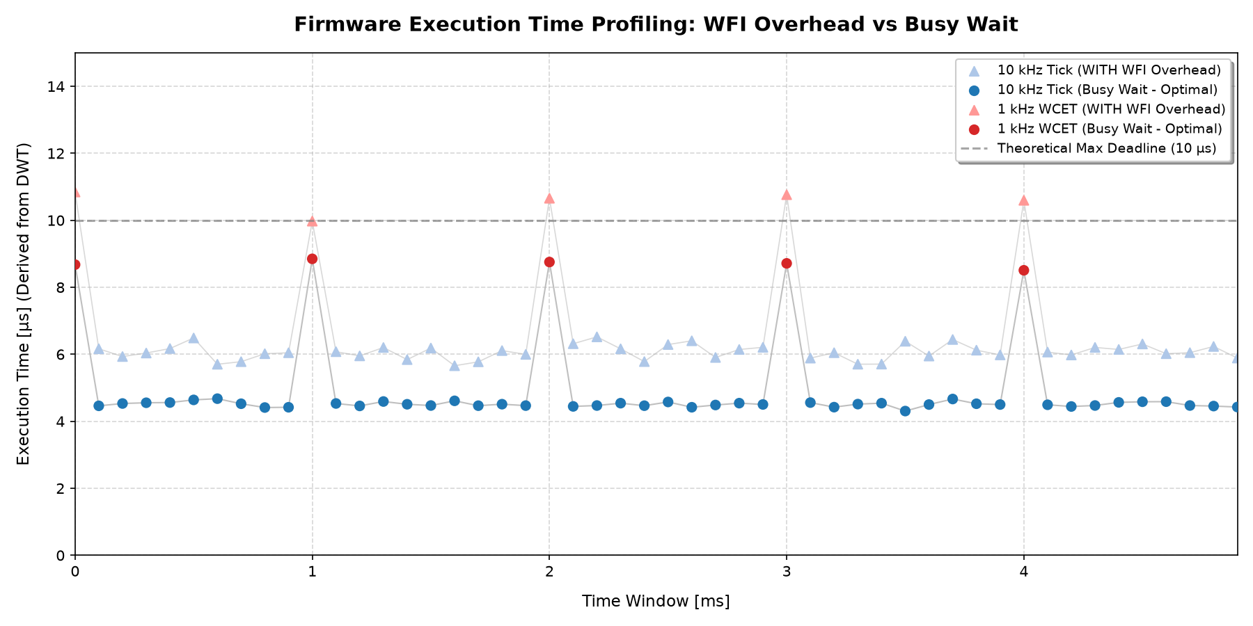
The main control timer (TIM6) fires at 10kHz, establishing a rigid, non-negotiable execution window of 100\(\mu\)s. Failing to conclude all control operations within this timeframe would cause interrupt overlap and catastrophic mechanical drift. Figure 10 shows the execution footprint over a 5 ms window, highlighting the intentional architectural asymmetry of the dual-loop design.
The system exhibits two distinct execution states:
Standard Execution (10 kHz): Represented by the blue baseline, 9 out of 10 interrupt cycles consume an average of 4.5 \(\mu\)s. During this brief window, the MCU parses the DMA-streamed rotary encoder data, computes the inner velocity PIDs for the DC motors, and updates the stepper timers’ hardware registers (
ARR/CCR) for step generation.Worst-Case Execution Time (at 1 kHz): Every tenth cycle (red peaks), the slower outer position loop triggers. The CPU must additionally fetch the linear encoder hardware timers, compute the position PID, format the 96-byte SPI telemetry payload, and calculate the 69-byte XOR checksum. Even under this peak computational stress, the execution time stabilizes around 8.8\(\mu\)s, safely below the 10\(\mu\)s reference limit.
In particular, it is possible to study the required execution time of specific functions by means of the DWT tool:
- Rotary Encoder Parsing (
update_rotary_encoder) - Velocity Loop (
PID_compute_vel): \(\sim 0.5\mu\)s per axis. It includes error calculation, integral clamping, low-pass filtering on the derivative term, and feedforward addition. - Position Loop (
PID_compute_pos): \(\sim 0.4\mu\)s per axis. - Stepper Control (
stepper_loop): \(\sim 0.6\mu\)s per axis. The conversion from velocity to hardware frequency and the dynamicARR/CCRregister updates are executed purely through rapid memory-mapped I/O writes. - Telemetry Checksum (69-byte XOR): \(\sim 0.2\mu\)s. Handled sequentially inside the CPU registers.
With the WCET securely confined under 10 \(\mu\)s, it highlights a massive architectural safety margin. Even in the absolute worst-case scenario, the motor control logic consumes less than 10% of the 100 \(\mu\)s interrupt window. This leaves the CPU idle for over 90 \(\mu\)s per cycle, providing margin to handle the asynchronous DMA callbacks, cache invalidation routines, and any future expansion of the kinematic complexity without ever threatening the deterministic nature of the machine.
Furthermore, to preserve this low latency, the firmware is intentionally designed to perform a busy wait within the main while(1) idle task, completely avoiding low-power sleep instructions such as WFI (Wait For Interrupt). Entering and exiting a sleep state introduces a wake-up penalty and an unpredictable jitter of \(1.5\) to \(2.0~\mu\)s due to core clock reactivation and context restoration. In a high-performance manufacturing application with abundant power supply, sacrificing determinism for negligible power is unjustified.
6 Conclusions
The development of the Axes Controller Board (ACB) successfully demonstrated that strict computational decoupling is a highly effective approach for advanced multi-axis mechatronic systems. By offloading path planning and kinematics to a high-level processor (Raspberry Pi 5) and isolating the hard real-time motor control on a dedicated bare-metal microcontroller (STM32H7), the inherent limitations of standard commercial controller boards were completely bypassed.
On the hardware level, the custom 4-layer PCB design, combined with strict star-grounding topologies and SPI daisy-chain series termination, proved robust against the severe electromagnetic interference (EMI) generated by high-power DC and stepper motors.
On the firmware level, the aggressive use of DMA controllers and hardware features, eliminated CPU polling overhead. The hardware-level DWT timing evaluation conclusively validated the system’s determinism: even during the worst-case scenario for Execution time, the complete multi-axis cascaded control loop executes in under 10 \(\mu\)s. This consumes less than 10% of the 100 \(\mu\)s deadline dictated by the 10kHz operating frequency, providing unparalleled stability.
7 Future Developments
7.1 Current Sensing
Future developments will focus on leveraging the onboard ACS37800 current sensors to implement sensorless collision detection and real-time torque monitoring, further enhancing the closed-loop capabilities of the Dedalus system without compromising its hard real-time guarantees.
7.2 SPI multi-target Packet
Currently the Raspberry Pi sends a single packet to the ACB at 1kHz frequency. Experiments show that the communication is robust thanks to real-time algorithms implemented by both sides. A faster control could be implemented, so the SPI communication may become the real-time bottle-neck. In order to overcome this problem, the Raspberry could send a packet that includes a set of consecutive targets: thanks to that, the ACB can schedule them at its own frequency, by carrying the communication’s computation burden one time for a full set of targets. This windowing-approach will make the communication much more robust to higher frequencies.
7.3 IMU implementation
In order to understand better the accelerations that affect the printing plate, an Inertial Measurement Unit can be added. It would help to smooth the commanding torque to both DC and stepper motors.
7.4 High Frequency Filtering
Currently, the AS5048A rotary encoders are fetched in the 10 kHz control loop. Due to the noisy environment generated by the high-current actuator wiring, it would be beneficial to acquire the encoder data at a higher frequency (e.g., 20kHz to 50kHz). These oversampled readings could then be mathematically filtered within the temporal window of the main control loop. In this way, the PID controllers would be fed with clean, pre-filtered positional data. A possible software implementation would involve a dedicated decimation filter, such as a Moving Average or a higher-order Low-Pass Filter, carefully tuned to aggressively attenuate noise without introducing an excessive phase delay that could compromise the system’s mechanical stability.
7.5 Mechanics
The two additional axis (A and C) are structured as direct-drive between the motor axis and the actual plate structure. This implementation is sub-optimal because it is very sensitive to environment vibrations. In order to achieve positioning stiffness on these 2 axis, a blocking reduction is required: A possible, simple solution could be to add a gearbox on the motors head. It is indeed a fast solution, but space constraints make it an impossible solution. The most feasible solution is to add a pulley reduction: the only vibrations that the plate structure will suffer, would come from the pulley stiffness. For this reason, a stiff pulley would be required.